|
Introduction
In this paper, the checksum is used with a different meaning.
Under our approach, for each output, its checksum represents
the number of either 00s or 10s corresponding to the given input
setting. In fact, such a checksum would cover a (contiguous)
range of inputs and involve a distinct count for each output. It
will be able to detect and also to locate stuck-at-0 and stuck-at-1 faults. Figure 1 illustrates our new scheme for checksum
testing.
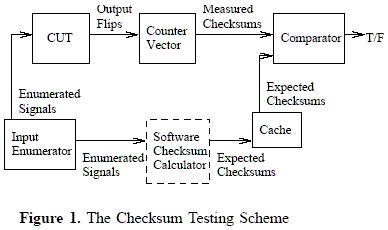
A pair of inputs, called enumerated signals, specifies a test
range for the circuit under test (CUT), together with a vector of
counters for each output to accumulate the number of either 00s
or 10s encountered. At the end of each testing, the accumulated
counters are compared with the expected checksums from the
cache, generated apriori by a software checksum calculator.
The comparison between the algorithm and the testing machine
should be efficiently real-time coordinated. Section IV
discusses the cases which might appear in practice, depending
whether the testing machine and the checksum algorithm can
be synchronized, or one of them is faster than the other.
Any mismatch with the checksums indicates a definite fault,
while a match on the checksums increases our confidence
on the circuits correctness. Each checksum test plan can
either be computed before hand and stored, or generated on
the fly. Compared to the pairwise approach to testing, the
storage requirement of checksums is considerably smaller. For
example, 216 expected results for the pairwise approach will
require 64K x 4 bytes memory involving 32 bit input and
output, while checksum results need only 32x2 bytes cache
The Counting Algorithm
Step 1.
As we wrote in the Introduction, the number of test patterns
can be controlled, before starting the effective test pattern
generation, according to the memory limitations of the testing
machine. To do so, we split the set of inputs, Vinp, into two
disjoint sets: variables (V1inp), and constants (V2inp), namely
Vinp = V1inp U V2inp and
V1inp Ç V2inp =
Æ. The set V1inp is
called the current frame of our test plan. A set of frames is
called a frame test and the process of doing a frame test is a
test pattern generation (Figure 3). However, we can design a
series of test frames which slides through the entire input set,
such that all the inputs are present as variables in one or more
of the test frames. A full frame test consists of a set of frames
such that any input variable appears unbounded in at least one
frame of the frame test. We say that a frame is complete if
it contains all inputs, namely V1inp = VinpVinp and
V2inp= Æ. As
expected, for large combinational circuits, the testing of the
complete frame is impracticable .
Application how-to:
Apply the input assignments to the combinational circuit specification (frame approach):
| |
input |
output |
| java selection |
<BLIF specification> <input assignment> |
<Frame BLIF specification> |
Step 2.
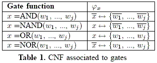
The CNF formula of a combinational circuit is the conjunction
of the CNF formulas for each gate output, where
the CNF formula of each gate denotes the valid input-output
assignments to the gate (Table 1).
Applicatio how-to:
Generate the clausal formula corresponding to the frame BLIF specification.
| |
input |
output |
| java gfc |
<frame BLIF specification> |
<Clausal formula> |
Step 3. The algorithm
Input: A CNF formula F over V corresponding to a combinational
circuit, a checksum testing machine able to test a
combinational circuit, and N the number of frames;
Output: The chip has a stuck-at-0/1 leading to output x.,
for some x.
1. split Vinp into two disjoints sets, V1,iinp and
V1,iinp, that is
Vinp = V1,iinp U V2,iinp
and V1,iinp Ç V2,iinp;
2. make some settings for the variables of V2,iinp, and denote
the corresponding clausal formula by Fiinp;
3. (tester task) let mc0[x] be the measured checksum provided
by the checksum testing machine corresponding to the input
given by V1,iinp and V2,iinp and to the output x bounded to 0.
Then mc1[x] = 2^|V1,iinp - mc0[x];
4. F' = F U Fiinp; detV(F') = 2(|Vinp| - |V2,iinp|
;
5. for (any x Î Vout) {
6. detV (F' U {¬x}) = detV (F')+ incV ({¬x}, F');
7. detV (F' U {x}) = detV (F')+ incV ({x}, F');
8. if (detV (F' U {¬x}) != mc0[x]) print
The chip has a stuck-at-0 leading to output x.
9. if (detV (F' U {x}) != mc1[x]) print
The chip has a stuck-at-1 leading to output x. }
Application how-to:
Apply the counting algorithm to the given clausal formula.
| |
input |
output |
| java testing |
<clausal formula> |
<expected checksum> |
Real-time execution coordination
Let F be a arbitrary frame, and let Tm(F), Ta(F) be the
times spend by the testing machine and the checksum algorithm,
respectively, in order to measure the two checksums. To
have an agreement between the two time values, we denote by
ad the accepted delay. If ad is small enough, then it is very
likely that the testing machine and the checksums algorithm
can be mutually synchronized one to the other. Depending on
these time values, we have two general cases:
- If |Tm(F) - Ta(F)| < ad, for all frames F, then we say
that the testing machine correlates with the checksums
algorithm (|x| means the absolute value of x);
- Otherwise, we may distinguish three situations:
- For all frames F, we have Tm(F) £ Ta(F), that
is, the testing machine is faster than the algorithm.
Then the proposed solution is to store in a memory
array all the measured checksums corresponding to
the testing machine. When the algorithm provides a
determinant, this will be checked with the already
saved checksums.
- For all frames F, we have Tm(F) ³ Ta(F), that
is, the testing machine is slower than the algorithm.
Then the algorithm should have the posibility of
storing in a memory array all the determinants corresponding
to the frame F. When the testing machine
provides a measured checksum, this will be checked
with the already saved determinants.
- For some frames F1, we get Tm(F1) £ Ta(F1),
whereas for other frames F2, we get Tm(F2) ³ Ta(F2), that is, the testing machine execution time
may vary compared with the checksum algorithm
execution time, from one frame to a different frame.
In other words, for some frames, the testing machines
is faster than the checksum algorithm, whilst for
other frames the converse holds. In tihs case, we
need to store in memory for each frame the measured
checksums and the determinants for later comparisons,
respectively.
Whether the testing machine and the checksum algorithm
are correlated or not, the algorithm for computing the checksums
must be efficient. The main design of the testing machine
is described in Figure 1. In principle, we suppose the testing
machine is augumented with an integer array able to store
the measured checksums (this is easy to be achieved since
the array needs a small amount of memory). Next, we shall
focus on efficient implementation of Algorithm A, based on
Proposition 3.1.
The size of the frame in Algorithm A should be correlated
with the run-time of the testing machine, represented by
step 3. The smaller frame will choose, the faster run-time
execution for computing the determinant at steps 6 and 7 will
be. Both values of detV (F' U {¬x}) and mc0[x] should be
known (almost) at the same time. In this way, we say that
the efficiency of our approach is dependent on the real-time
execution coordination between the algorithm and the testing
machine.
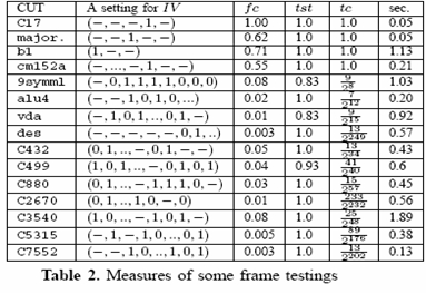
For tractable testing, we conducted a frame
test with V{inp}2 being a non-empty set.
Of course, the bigger
V{inp}2, the faster execution time for ECFCC.
Table 2 shows the execution times (in seconds) of ECFCC (last column) for
some random frame settings of the IV.
The last but one column shows the testability cost according to the
frame's size. The smaller each frame, the closer tc is to 0,
giving us a small testability cost.
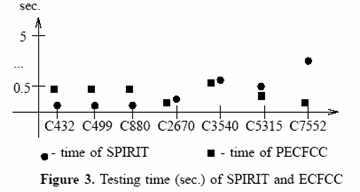
Compared to SPIRIT [GiF2002], our approach has excellent testability
and execution testing time, and good fault coverage.
For example, Figure 3 presents a comparison between SPIRIT and our tool
(ECFCC). On the horizontal axis are the combinational circuits and on the vertical
axis is the testing time of the corresponding combinational
circuit. So, ECFCC is better than SPIRIT regarding the testing
time for C2670, C3540, C5315 and C7552, having close performance with SPIRIT
for the rest of the circuits. We may say that the larger combinational
circuit, the better performance our approach has compared with SPIRIT.
|